
Web Guide Actuator Stroke: How to Choose the Correct Travel Range
Selecting the appropriate stroke is the key to choosing the right web guide actuator.
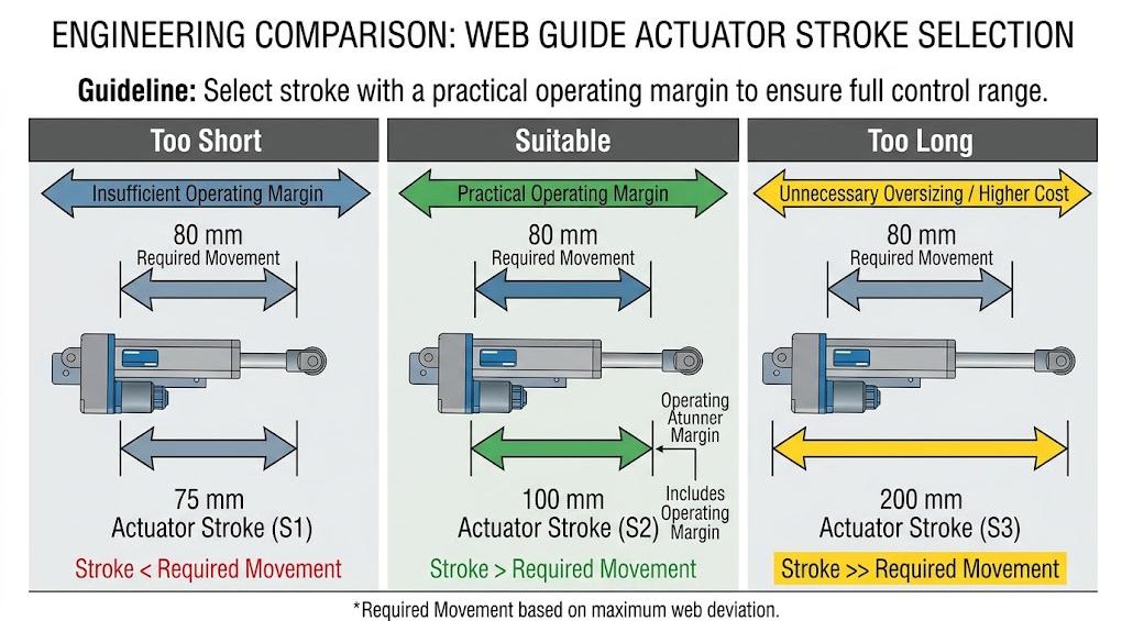
If the stroke is too short, the actuator may not be able to provide sufficient movement to correct the roll deviation; if the stroke is too long, it will increase the installation space and cost, but may not improve the guiding performance.
So, how long should the actual stroke be?
This depends on the maximum correction amount, the geometric shape of the guiding mechanism, the machine configuration, and the required operating margin.
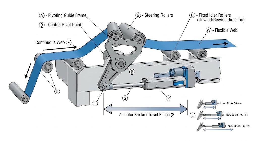
Table of Contents
What Does Web Guide Actuator Stroke Mean?
The actuator stroke refers to the maximum linear movement distance from one end to the other of the actuator. In the sheet guiding system, this movement is transmitted to the steering rollers, guiding frames or other mechanical components, causing the sheet to undergo lateral movement.
For a simple 1:1 mechanical structure, it can be estimated as follows:
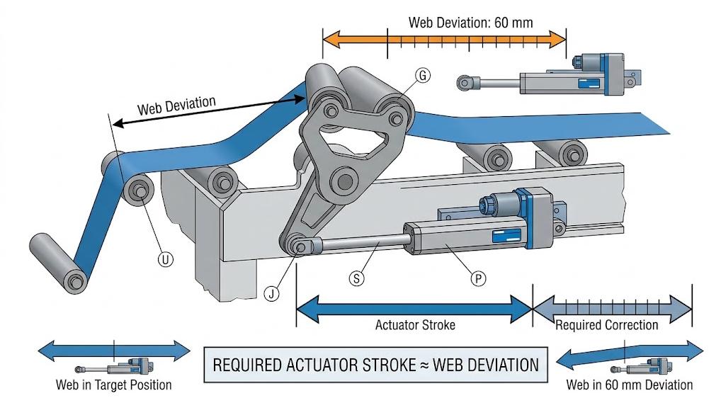
Required actuator stroke ≈ Maximum required correction amount
For example, if the guiding mechanism requires the actuator to move 60 millimeters to correct the maximum sheet deviation, then a stroke of at least 60 millimeters is necessary.
However, many sheet guiding mechanisms adopt mechanical structures such as pivot points, lever arms, etc. In this case, the actuator stroke is not necessarily 1:1 with the actual sheet correction amount. Therefore, before selecting the actuator, the geometric relationship of the guiding frame should be considered first.
4 Factors That Determine the Right Stroke
1. Maximum Web Misalignment
First, determine the maximum distance by which the size of the sheet may deviate from the target position during normal operation.
For example:
- ±20 mm correction requires a maximum total movement of 40 mm.
- ±30 mm correction requires a maximum total movement of 60 mm.
- ±50 mm correction requires a maximum total movement of 100 mm.
Note to distinguish between the unilateral correction amount and the total travel of the actuator. If the system needs to correct 50 mm from the center position in either direction, the required travel may exceed 50 mm, depending on the mechanical structure.
2. Guiding Mechanism Geometry
The actuator usually does not directly move the area but pushes the guiding frame or steering roller to convert the actuator’s movement into the lateral correction of the area.
The following factors should be mainly considered:
- Actuator installation position
- Axis point position
- Lever arm length
- Guiding roller position
- Mechanical motion ratio
For example, when the distance between the actuator and the axis point, or the actuator and the guiding roller is different, the same actuator travel may produce different lateral correction amounts.
Therefore, the actuator travel should be calculated based on the actual guiding mechanism, rather than being determined solely based on the area deviation.
3. Width and Machine Configuration
The width does not directly determine the stroke of the actuator. The width of the actuator’s range does not necessarily require a longer actuator with a greater stroke.
However, the width of the actuator’s range might require processing on a larger guide roller frame, and the machine layout might require a larger correction stroke. Therefore, the relationship between width, roller size, frame geometry, and the expected lateral deviation should be evaluated as an integrated system.
The same principle also applies to small processing equipment and large industrial wide-format processing lines: the required stroke depends on the machine design and the correction range, not just the width.
4. Operating Safety Margin
Avoid choosing an actuator that operates continuously at the maximum stroke or close to the maximum stroke.
Assume your calculation indicates a need for approximately 80 mm of actuator stroke. A 75 mm stroke provides almost no additional operating margin, while a 100 mm stroke might be more practical.
The goal is not to select the longest available stroke, but to provide sufficient available correction range while ensuring the actuator is within a comfortable operating range.
Common Web Guide Actuator Stroke Options
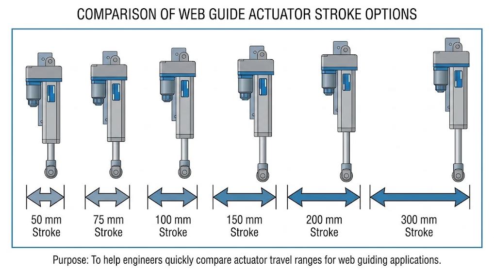
Different web guiding applications require different travel ranges. Common options include:
| Stroke | Typical consideration |
| 50 mm | Compact machines and small correction ranges |
| 75 mm | Small to medium correction requirements |
| 100–150 mm | Common industrial applications |
| 200 mm | Larger correction requirements |
| 300 mm | Large guiding frames and demanding applications |
These are general references rather than fixed rules. The appropriate stroke should always be confirmed based on the actual machine geometry and required correction range.
What Happens If the Actuator Stroke Is Too Short?
The small size of the actuator may cause the following problems:
- The sheet material cannot return to the target position.
- The actuator frequently approaches the mechanical travel limit.
- The correction capability is limited.
- The controller repeatedly issues movement instructions but fails to reach the target position.
If the actuator frequently reaches the travel limit during normal production, it may indicate that its size is insufficient. However, before replacing the actuator, it is also necessary to check whether the sheet material deviation is too large, whether the sensor position is correct, and whether there is an alignment problem in the mechanical system.
What Happens If the Stroke Is Too Long?
A longer travel is not necessarily better.
An excessively long actuator requires more installation space and will increase equipment costs and the difficulty of mechanical integration, but it does not necessarily improve the guiding accuracy.
For the sheet material guiding system, the goal is not to pursue the maximum travel, but to obtain an adequate effective correction range.
How to Choose the Right Web Guide Actuator Stroke
When choosing an actuator, the following five steps can be followed:
- Step 1: Determine the maximum expected amplitude deviation.
- Step 2: Calculate the required lateral correction amount.
- Step 3: Check the mechanical movement ratio of the guide frame.
- Step 4: Add a reasonable operating margin.
- Step 5: Compare the calculated results with the available actuator stroke.
For example, if after considering the geometric shape of the guide frame, an actuator stroke of approximately 70 mm is required, a 75 mm stroke margin is relatively small, while a 100 mm stroke can provide a more practical operating range. If the calculated requirement is approximately 130 mm, a 150 mm stroke would be more suitable.
It should be noted that stroke is only one factor in actuator selection. Other factors such as thrust, speed, positioning accuracy, installation size, limit settings, and controller compatibility should also be checked.
FAQ
Q1: Is a longer actuator stroke always better?
Not necessarily. The stroke should meet the required correction range and avoid choosing an overly large stroke.
Q2: How to calculate the actuator stroke?
First, calculate the required correction amount, then combine the geometric shape of the guide frame, and add a reasonable operating margin.
Q3: What length of actuator stroke should be chosen?
Common options include 50, 75, 100, 150, 200 and 300 mm, depending on the application and machine design.
Q4: Can a 150 mm actuator replace a 100 mm actuator?
Not necessarily. Before replacement, check the stroke, thrust, speed, installation dimensions and controller compatibility.
Need Help Choosing the Right Actuator Stroke?
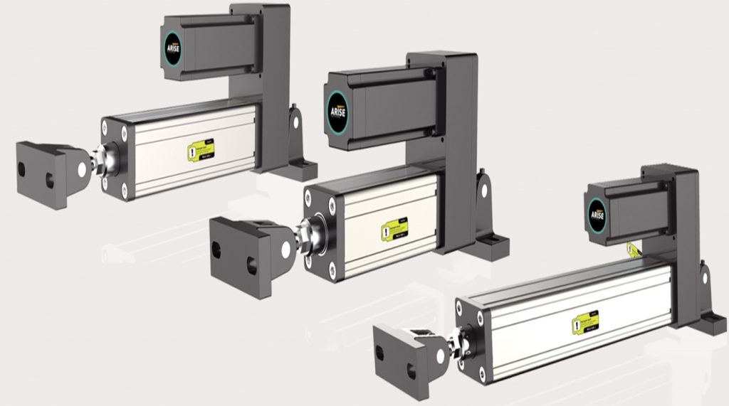
Arise offers web guide actuators with different stroke configurations for a wide range of web guiding applications. When selecting a model, consider the required stroke together with thrust, speed, positioning accuracy, mounting configuration, and control compatibility.
Explore the Web Guide Actuator range to find a suitable configuration for your application.